Preparation of a catalyst ink for manufacturing a catalyst coated membrane (CCM)

Preparation of a catalyst ink for manufacturing a catalyst coated membrane (CCM)

Applicant: TEMASEK POLYTECHINC [SG] / WO 2023014300 A1

This patent application from Temasek Polytechnic looks to overcome problems with the existing methods for preparation of a catalyst coated membrane (CCM). Transfer of electrocatalyst layers via a flexible substrate to the membrane surface is the first of these methods (roll-to-roll or decal). Roll-to-roll has the downside of requiring multiple complex stages and high cost. The decal method can lead to poor dispersion of catalyst particles, incomplete transfer of catalyst onto the membrane and catalyst degradation during the hot-pressing process. The direct spray deposition of catalyst onto the membrane surface might relieve some of the complexity however, this is time consuming and the need for several different inks can result in high catalyst wastage, increased likelihood of defects and structural issues, as well as agglomeration and nozzle blockage during the spraying process. This patent application refers to work to improve the direct spray method incorporating milling steps to reduce the problem of nozzle blockage.

Based on a desired ionomer weight percentage of 40% (c.f. catalyst powder), a method is used whereby 6.25 g of catalyst powder (Tanaka TEC10V40E, 40 wt.% Pt/C), is dispersed in 15 g of deionized water and ground with zirconia balls in an enclosed grinding bowl with addition of 50 g of Nation solution (79.61 g Chemours D520, 5% Nation by weight). Then ball milled in a planetary ball mill PM 100 at room temp. with a rotation speed of 300 rpm for 5 min (total time of 10 min inclusive of a 1 min interval). The obtained ink mixture can then be filtered through a 400-mesh filter. The filtered ink is then mixed with 30 g of isopropanol (IPA) and sonicated at 25 kHz, room temp. for 15 min using an Elma Multi-frequency ultrasonic unit (Model: TI-H-10) to produce a homogenous catalyst ink with the desired viscosity. Then primed in an ultrasonic syringe holder for at least 30 mins before spray coating. The spray coating is carried out by spraying multiple coats on each side of the membrane using a Sono-tek XYZ motion ultrasonic coating systems (Model: ExactaCoat). The number of coats may be calculated based on the loading of catalyst required [which differs for the cathode size (e.g., 0.4 mg/cm2) and anode side (e.g. 0.1 mg/cm2)]. A single spray cycle of 3 mL ink on a 20×20 cm membrane achieves 0.1 mg/cm2 catalyst loading. The catalysts were incorporated into an air-cooled open-cathode PEMFC stack consist of 5 cells in series with an active area of 8 cm2 for testing.

The above system is referred to as the “three component ink formulation”. In another example, the isopropanol was added prior to ball milling and referred to as the “four component ink formulation”. The three-component system performed best in electrochemical testing, likely due to the mixture for the ball mill being too dilute for complete homogenisation.

The work is important because it improves and simplifies the production process for CCM. When the market is at full scale, it will be important for higher throughput and lower downtime in a fuel cell production plant, and this work would improve those factors.

Electrode for fuel cell comprising non-platinum catalyst and graphene layered structure, and membrane-electrode assembly comprising same

Electrode for fuel cell comprising non-platinum catalyst and graphene layered structure, and membrane-electrode assembly comprising same

Applicant: KOLON INC [KR] / WO 2023018126 A1

This patent application from Kolon refers to a non-platinum catalyst system from a PEM fuel cell. The electrode for a fuel cell of the present invention has a structure in which a catalyst layer and a graphene layer are stacked and alternately laminated, and the conductive polymer is intended to improve the catalyst efficiency by limiting the transition metal particle size.

The catalyst is prepared by mixing CNT as a carbon support, iron(III) phthalocyanine chloride as an Fe—N precursor (M—N precursor) in a mass ratio of 1:2. Then, dispersing in aniline a mass ratio of 2:1 using distilled water as a solvent, and drying at 60° C/8 h to obtain a solid powder. Then heat-treating at 800 ° C/3 h under N2. Then dispersing with Nafion PFSA ionomer, distilled water, and normal-propyl alcohol and spray drying with a graphene dispersion in the first nozzle and the catalyst dispersion in the second nozzle. The graphene layers is sprayed first onto a release material of FEP (Fluorinated Ethylene Propylene) to form a graphene layer, then the catalyst layer is sprayed onto the graphene layer. This process is continued until there are 100 layers. The spray drying is carried out with a mist size of 10 μm at an ultrasonic frequency of 180 kHz. The syringe pump flow rate was set at ~1 ml/min, a nozzle moving speed of 10 m/s, and an air pressure of 4 L/min.

A membrane-electrode assembly (MEA) was then prepared by applying the formed electrode layer as a cathode electrode part and a Pt/C electrocatalyst as an anode electrode part by thermally compressing the polymer electrolyte membrane (PEM).

Performance evaluation was performed under the conditions of a temperature of 65° C., air pressure of 100 kPa, RH of 100%, and a H2/air flow rate ratio of 1.5/2.0. The performance improved when the Fe-N precursor was changed to a Co-N precursor (Example 2) and even further when a Mn-N precursor (Example 3) was employed.

This work is of high importance because the use of scarce platinum group metals (PGM) raises the cost and potentially reduces the overall deployment possible of PEM fuel cells (and PEM electrolysers). The use of a dual spray nozzle simplifies the production method. It is interesting that Manganese (Mn) performed best because although the demand for high purity Mn including for lithium-ion batteries is increasing, the metal still has lower criticality than either Pt or Co.

Proton Conductive Material

Proton Conductive Material

Applicants: UNIV HOKKAIDO NAT UNIV CORP [JP] / TOYOTA MOTOR CO LTD [JP] / DE 102022119191 A1

This application from Toyota looks to overcome the need for humidification for proton conductive materials. The degree to which this was achieved was tested by immersing in water at 80°C for 1 hour, air drying for 4 days and vacuum drying for a further 24 hours, then weighing the sample. The membrane can be prepared from two different polymers – one being a proton source and the other being a proton channel. Several different chemical groups can release protons, in this case the sulfonic acid group (-SO3H) is preferred and attached to a styrenic group e.g., styrene sulfonic acid (SSA) as shown in Schema 1 below. This type of polymer is chosen because it can form a stacked structure through π-π interactions. The proton channel polymer needs to be able to coordinate protons such as methylene bisacrylamide (MBAA) and is added at 1 part per weight of SSA-Na.

Figure 1

The polymerisation reaction requires an initiator and AMHEPA as shown in Schema 1 below is employed for this purpose. The resulting polymer gel is then treated with 3M aq. HCl and water and vacuum dried for 24 hrs to obtain the final membrane polymer – PolySSA/MBAA. This polymer exhibited 2.9% water loss on testing, however this was presumed due to inadequate drying, and the water resistance would be even higher (although a repeat experiment was not reported).

The work is important for improving the durability of the fuel cell and to prevent disintegration after storage at room temperature, thereby reducing the failure rate and improving the lifetime characteristics.

Schema 1

Kaijin Energy Technology Co Ltd Sodium Ion Battery Technology

Kaijin Energy Technology Co Ltd Sodium Ion Battery Technology

Kaijin Energy Technology Co Ltd based in Dongguan, China, was founded in March 2012. It is a high-tech enterprise in China specialising in R&D, production, and sales of anode materials for mobility, energy storage and portable electronics. Kaijin’s anode materials are designed to have high capacity, high temperature performance, excellent cycling performance and good safety performance. The products cover anode materials for square, cylindrical, soft pack polymer and other types of lithium-ion batteries.

Kaijin’s recent patent applications describe a technology for self-filling pores of a merchant graphite material using negative pressure. The work looks to overcome the challenges of utilising silicon in anodes i.e., volume expansion and resultant cracking and chalking which cause the anode material to lose contact with the current collector, resulting in a sharp decline in cycle performance.

In addition, silicon material has low intrinsic conductivity which leads to poor rate performance. The patent applications (CN112563501 A, CN112563503 A) describe a production method which makes a silica phase by spray pyrolysis to form silica nanoparticles and mixes those with a dispersing agent and a binder in a solvent to obtain a uniformly dispersed precursor. Secondly a “puffed/emulsified” graphite is prepared. This material is more commonly known as “expanded graphite” and is multiporous with pores as large as 2 mm which can easily be intercalated by polymeric materials to form composites. (Zheng, Yu, & Yang, CN112563501A, 2021a), (Zheng, Yu, & Yang, 2021b) The expanded, emulsified graphite is added to the dispersed silica precursor under vacuum which forces the silica precursor into the graphite’s pores. This gives a paste which is spray dried and mixed with carbon coating material, calcined, and screened to the desired size to provide an anode material with a pomegranate appearance and a garnet structure. The material obtained is claimed to provide an anode with a high initial efficiency, low volume expansion, improved conductivity, rate performance and long cycle life. The carbon coating on the outside layer also prevents direct contact between the nano silicon and the electrolyte.

Preparation methods which overcome the outstanding issues with cracking, and which can be scaled cost effectively provide a significant competitive advantage for anode manufacturers. High tech enterprises are on the forefront of such innovations.

Other KAIJIN patent filings including WO2022121137A1 describe preparation processes for one-dimensional porous silicon-carbon composite anode materials with good performance in terms of reversible specific capacity and cycle stability. The materials are prepared by using nano-SiO2 with polyacrylonitrile processed using electrospinning which results in a material with a shorter lithium-ion transmission distance and lower volume expansion problem, improved structural properties and cycling characteristics. (Ge & Yang, 2022)

Tests on the material indicated that reversible capacity of the silicon/carbon composite material can be selectively regulated by the amount of silicon source introduced. A first reversible specific capacity greater than 750 mAh/g was obtained, the first cycle coulombic efficiency was greater than 86% and the capacity retention was 84% after 100 cycles.

Ge, C., & Yang, Y. (2022, June 16). WO2022121137A1. One-dimensional porous silicon-carbon composite negative electrode material, preparation method, and application thereof.
HiNa Battery. (2018). R&D Achievements. Retrieved from HiNa Battery: https://www.hinabattery.com/en/index.php?catid=15
Nannan, Z. (2019, April 1). China First Demonstrates the 100 kWh Na-Ion Battery System for Energy Storage. Retrieved from Chinese Academy of Sciences: https://english.cas.cn/newsroom/research_news/201904/t20190401_207399.shtml
Wu, K., Dou, X., Zhang, X., & Ouyang, C. (2022). The sodium-ion battery: An energy-storage technology for a carbon-neutral world. Engineering, Pre-proof.
Zheng, A., Yu, D., & Yang, Y. (2021a, Mar 26). CN112563501A. Pomegranate-like structure silicon-based composite material, and preparation method and application thereof.
Zheng, A., Yu, D., & Yang, Y. (2021b, March 26). CN112563501A. Pomegranate-like structure silicon-based composite material, and preparation method and application thereof.

DSM Patents High Performance Silver-Free PV Back Layer

DSM Patents High Performance Silver-Free PV Back Layer

DSM Patents High Performance Silver-Free PV Back Layer

DSM, HQ Neerlen, Netherlands has a patent family relating to production of an electro-conductive back-sheet comprising either pure copper or a copper-aluminium metal layer for a photovoltaic (solar) cell. The cell is reported in the patent to have a high oxygen transmission rate (OTR). The patent family which has a priority date of 6th October 2017, has been filed in the USA, Spain, Europe, China, Hong Kong, and India. The latest patent publication number is WO2019068934A11.

Photovoltaic (PV) modules are at the heart of solar power systems and consist of a core layer encapsulated in laminate designed to protect against mechanical and weathering-related influences. The encapsulation consists of a glass front layer with an ethylene-vinyl acetate (EVA) copolymer and a glass or polymeric back layer which shields against UV light, moisture, and oxygen. Typical back sheets are made from fluoropolymer and polyesters (e.g., polyethylene terephthalate (PET).

PV modules comprising EWT (emitter-wrap-through) or MWT (metal-wrap-through) or IBC (interdigitated back-contact) solar cells contain an electrically conductive patterned back sheet for which connect to electrical contacts on the solar cell back surface. such a back sheet comprises a polymer layer and a patterned conductive layer made of copper (or copper alloy). There has been a desire to decrease or replace the copper due to its increasing cost. Aluminium is an alternative however it has poor solderability and high contact resistance, and so a thin layer of copper is thermally sprayed onto the aluminium e.g., from Hanita Coatings. The downside of this approach is thermal degradation, high resistance due to increased oxygen transfer rate (OTR) and corrosion issues especially in more humid settings. This results in lower power output. The polymers can be adjusted to achieve an OTR of less than 20 cm3/m2.atm per day but these have decreased hydrolytic resistance and UV stability which adversely affects the durability and lifetime of the module.

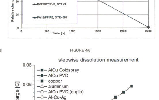
Figure 1: Results on the Damp Heat Resistance with High OTR PA/PP/PE vs. PET and Stepwise Dissolution Measurement for Cold Sprayed Cu/Al conductive sheet vs other metal formulations1

To overcome this issue, the inventors developed a cold-spray deposition method for the copper which allows for layers to be built up quickly, under atmospheric conditions and at low cost. In addition, using polyamide (PA)/polypropylene (PP)/polyethylene (PE) polymers with high OTR’s (384 are used as the back sheet polymer and these are compatible with the Cu/Al of the invention.

Results on power decay were superior to several other formulations including Al/Cu prepared by standard vapour deposition, pure copper, pure aluminium, or Al-Cu-Ag. Good mechanical performance was achieved after 2,000 hrs of ageing. Even though UV resistance was similar, damp heat resistance was far better with the PA/PP/PE layer compared with PET. The results are shown in Figure 1. above.

  1. Van Duijnhoven, F, Henricus, G and Janssen, R. IN407312A1. Electro-Conductive Back-Sheet Comprising An Aluminium And A Metal Layer. Sept 30, 2022.
  2. Northstar. Northstar Awarded Patent by United States Patent and Trademark Office Protecting Its Front-End Process for Reprocessing Asphalt Shingles. Northstar Clean Technologies. [Online] Nov 8, 2022.
  3. NorthStar. Northstar Corporate Presentation. Northstar. [Online] Q4 2022a. https://docsend.com/view/e8c53v3mdyupcxg5.